Gliders
Overview
The overview of this project is to create a glider that will be able to fly with the right measurements for all necessary parts
Equipment
Computer
Engineering Notebook
Aery32 Program
Glue
Cutting Tool
Wood
Ruler
Play Dough
Engineering Notebook
Aery32 Program
Glue
Cutting Tool
Wood
Ruler
Play Dough
Design 1

It will fly!
The vertical tail may be larger than necessary.
The stabilizer may be larger than necessary.
The static margin for stability (0.014) is less than the recommended value (0.05).
(The glider may have marginal stability if the static margin is too close to zero.)
You may:
Move the wing farther aft, or
Add more mass to the nose.
Dimensions & Statistics
Aery Evaluation Number: 117
Fuselage Length: 30.00 cm
Wing Location: 13.00 cm
Stabilizer Location: 22.00 cm
Vertical Tail Location: 22.00 cm
Mass at Nose: 8.00 g
Center of Gravity Location: 17.36 cm
Neutral Point Location: 17.50 cm
ESTIMATED Mass: 41.87 g
Wing Loading 0.120 g/cm^2
Throwing Velocity: 20.00 km/hr
Flight Angle of Attack: 7.99 degrees
Stabilizer Incidence Angle: -0.22 degrees (positive upward)
ESTIMATED Stall Angle: 11.07 degrees
ESTIMATED Stall Velocity: 16.37 km/hr
ESTIMATED Glide Angle: 5.49 degrees (positive downward)
ESTIMATED CDo: 0.023
Wing Span: 35.00 cm
Planform Area 350.00 cm^2
Wing Root Chord: 10.00 cm
Wing Taper Ratio: 1.00
Wing Tip Chord: 10.00 cm
Wing Tip Sweep Distance: 0.00 cm
Wing Leading Edge Sweep Angle: 0.00 degrees
Wing Aspect Ratio: 3.50
CL,alpha: 3.71 1/radian
Stabilizer Span: 35.75 cm
Planform Area 228.80 cm^2
Stabilizer Root Chord: 8.00 cm
Stabilizer Taper Ratio: 0.60
Stabilizer Tip Chord: 4.80 cm
Stabilizer Tip Sweep Distance: 4.79 cm
Stabilizer Leading Edge Sweep Angle: 15.00 degrees
Stabilizer Aspect Ratio: 5.59
CL,alpha: 4.33 1/radian
Vertical Tail Height: 15.00 cm
Planform Area 102.00 cm^2
Vertical Tail Root Chord: 8.00 cm
Vertical Tail Taper Ratio: 0.70
Vertical Tail Tip Chord: 5.60 cm
Vertical Tail Tip Sweep Distance: 4.02 cm
Vertical Tail Leading Edge Sweep Angle: 15.00 degrees
Design 2

It will fly!
The static margin for stability (0.029) is less than the recommended value (0.05).
(The glider may have marginal stability if the static margin is too close to zero.)
You may:
Move the wing farther aft, or
Add more mass to the nose.
Dimensions & Statistics
Aery Evaluation Number: 163
Fuselage Length: 30.00 cm
Wing Location: 7.50 cm
Stabilizer Location: 22.00 cm
Vertical Tail Location: 22.00 cm
Mass at Nose: 8.45 g
Center of Gravity Location: 8.78 cm
Neutral Point Location: 8.90 cm
ESTIMATED Mass: 24.11 g
Wing Loading 0.120 g/cm^2
Throwing Velocity: 20.00 km/hr
Flight Angle of Attack: 6.62 degrees
Stabilizer Incidence Angle: -1.50 degrees (positive upward)
ESTIMATED Stall Angle: 7.69 degrees
ESTIMATED Stall Velocity: 17.91 km/hr
ESTIMATED Glide Angle: 2.74 degrees (positive downward)
ESTIMATED CDo: 0.016
Wing Span: 52.00 cm
Planform Area 200.20 cm^2
Wing Root Chord: 5.50 cm
Wing Taper Ratio: 0.40
Wing Tip Chord: 2.20 cm
Wing Tip Sweep Distance: 0.00 cm
Wing Leading Edge Sweep Angle: 0.00 degrees
Wing Aspect Ratio: 13.51
CL,alpha: 5.33 1/radian
Stabilizer Span: 5.00 cm
Planform Area 27.50 cm^2
Stabilizer Root Chord: 5.50 cm
Stabilizer Taper Ratio: 1.00
Stabilizer Tip Chord: 5.50 cm
Stabilizer Tip Sweep Distance: 1.44 cm
Stabilizer Leading Edge Sweep Angle: 30.00 degrees
Stabilizer Aspect Ratio: 0.91
CL,alpha: 1.42 1/radian
Vertical Tail Height: 3.50 cm
Planform Area 23.80 cm^2
Vertical Tail Root Chord: 8.00 cm
Vertical Tail Taper Ratio: 0.70
Vertical Tail Tip Chord: 5.60 cm
Vertical Tail Tip Sweep Distance: 0.94 cm
Vertical Tail Leading Edge Sweep Angle: 15.00 degrees
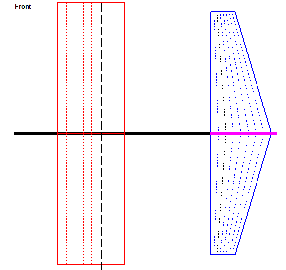
Design 3
It will fly!
The vertical tail may be larger than necessary.
The stabilizer may be larger than necessary.
The static margin for stability (0.011) is less than the recommended value (0.05).
(The glider may have marginal stability if the static margin is too close to zero.)
You may:
Move the wing farther aft, or
Add more mass to the nose.
Dimensions & Statistics
Aery Evaluation Number: 115
Fuselage Length: 30.16 cm
Wing Location: 5.00 cm
Stabilizer Location: 22.54 cm
Vertical Tail Location: 22.54 cm
Mass at Nose: 8.00 g
Center of Gravity Location: 9.96 cm
Neutral Point Location: 10.04 cm
ESTIMATED Mass: 19.38 g
Wing Loading 0.084 g/cm^2
Throwing Velocity: 20.00 km/hr
Flight Angle of Attack: 5.27 degrees
Stabilizer Incidence Angle: -0.06 degrees (positive upward)
ESTIMATED Stall Angle: 10.49 degrees
ESTIMATED Stall Velocity: 13.67 km/hr
ESTIMATED Glide Angle: 5.45 degrees (positive downward)
ESTIMATED CDo: 0.025
Wing Span: 30.16 cm
Planform Area 229.82 cm^2
Wing Root Chord: 7.62 cm
Wing Taper Ratio: 1.00
Wing Tip Chord: 7.62 cm
Wing Tip Sweep Distance: 0.00 cm
Wing Leading Edge Sweep Angle: 0.00 degrees
Wing Aspect Ratio: 3.96
CL,alpha: 3.91 1/radian
Stabilizer Span: 28.00 cm
Planform Area 137.20 cm^2
Stabilizer Root Chord: 7.00 cm
Stabilizer Taper Ratio: 0.40
Stabilizer Tip Chord: 2.80 cm
Stabilizer Tip Sweep Distance: 0.00 cm
Stabilizer Leading Edge Sweep Angle: 0.00 degrees
Stabilizer Aspect Ratio: 5.71
CL,alpha: 4.46 1/radian
Vertical Tail Height: 15.00 cm
Planform Area 114.30 cm^2
Vertical Tail Root Chord: 7.62 cm
Vertical Tail Taper Ratio: 1.00
Vertical Tail Tip Chord: 7.62 cm
Vertical Tail Tip Sweep Distance: 0.00 cm
Vertical Tail Leading Edge Sweep Angle: 0.00 degrees
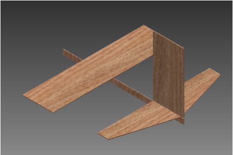
Glider design 3 Inventor Parts |
Glider Design 3 Inventor Assembly |
|
|
|
Glider Design 3 Drawings Parts(IDW)
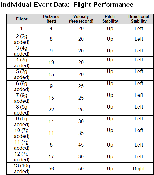
test Flight Data/Photos of Plane
|
|
Conclusion

Conclusion
1. Explain which glider or aircraft term were difficult to understand and the correct definition.
The Root Chord, and Tamper Ratio are parts in the AERY32 hardtop understand
2. Explain any challenges if someone else were to construct your design using the AERY print.
The only problem one would face if they wish to reconstruct my aery print is to put the dimensions as centimeters(cm)
3. Explain any challenges faced using the AERY software and how you overcame those challenges.
Change the measurements for all parts by the following---->
4. Was the glider as stable as you expected? Why or why not might this be so?
The Glider was not stable in the beginning because according to the data above the Glider would be shown to be flying towards the left and never go past 20ft. This is due to there not having enough weight in the nose of the plane, and another factor is the positions of where I place extra weight. Now after placing extra weight in the nose in correct positions it is able to reach 56ft maximum.
5. What techniques did you use to “trim” the glider for straight and gently descending flight?
The techniques I used to "trim" the glider was using play dough and sanding a portion of the horizontal stabilizer in order for the vertical stabilizer to be glued in place and become accurate enough to allow the plane to fly.
6. How many test flights were required to get the glider trimmed for long distance, straight-line flight? Was this expected? Why or why not?
There was a minimum of 10 test flights that had to be required to get the glider trimmed for long distance because without test flying the plane first you would not see a mistakes that could be fixed and improve. This number of flights was expected because all creations have flaws no matter how perfect or accurate the calculations are.
